 English
 русский
 عربى
عربى

Machine Applications
Applications of the Inverted Vertical Wire Drawing Machine
Why the drum sits above the operator, where that layout pays for itself on a production floor, and which wire types belong on a different machine altogether.
Ask anyone who runs a rod breakdown line what really limits output, and the answer is rarely drawing speed. It is coil handling. A wire rod coil that has to be lifted, threaded and discharged by hand will cap production long before the capstan reaches its rated speed. The inverted vertical wire drawing machine exists to remove that bottleneck: the die blocks and capstans sit above the working position, the wire leaves the final drum on a near-vertical downward path, and the take-up stands at floor level underneath.
The short answer first: inverted vertical machines are at their best where the input is heavy wire rod, the output is an intermediate or medium gauge, the finished packages are large, and the building is short on floor length but tall enough to work vertically. They are the wrong answer for very fine wire, for materials that need full wet immersion, and for small batches that cannot justify the foundation work. Everything below explains where those boundaries sit.
What Inverted Vertical Means on a Real Production Floor
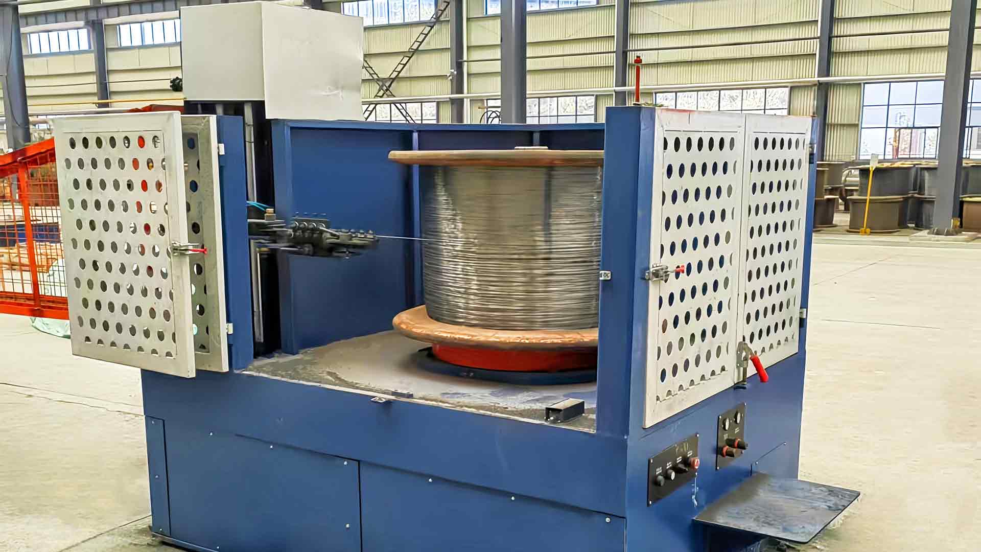
On a conventional straight-line machine, the wire travels horizontally through a row of capstans and then moves sideways into a spooler. On an inverted vertical machine, the drum sequence is stacked above the operator and the wire path turns downward at the last pass. The take-up, whether a spool, a plum blossom former or an elephant trunk winder, collects the finished wire below the drum instead of beside it.
Three consequences follow, and they drive almost every application decision:
- The wire falls into its package. Gravity assists the last section of the path instead of fighting it, so there is less lateral bending and fewer guide contacts between the final die and the take-up.
- Footprint per tonne of output shrinks. A vertical machine occupies a fraction of the floor length of a comparable straight-line layout, which matters when a line has to be squeezed into an existing bay.
- Coil handling becomes a vertical task. Pay-off at high level and discharge from below are efficient, but they assume the building has the headroom and the lifting equipment to support them.
The same logic runs through the whole family of inverted wire drawing machines, from single-channel units built around one clean wire path to multi-pass machines that carry a full reduction sequence on a single frame.
Where Inverted Vertical Drawing Machines Earn Their Place
Rod breakdown and first-pass reduction
The classic application is the first drawing pass after the steel mill. Wire rod arrives in heavy coils, and the machine has to reduce it to a workable intermediate gauge without asking the operator to manhandle the package at every change. A vertical machine feeds the rod from a high-level pay-off, draws it down through stacked die blocks and discharges underneath — a sequence that suits coils heavy enough to rule out a horizontal spooler.
Because the finished package is built below the drum, rod breakdown is also where downstream logistics are simplest: the coil is already positioned for transport to the next machine rather than requiring a sideways transfer from a spooler at head height.
Low-carbon steel for nails, mesh and binding wire
Most low-carbon wire ends up in a second product — nails, welded mesh, barbed wire, binding wire — and each of those downstream machines is sensitive to diameter tolerance and surface condition. Wire that varies in gauge will jam a nail die or throw a mesh loom out of register, so consistency matters more than peak speed. Inverted vertical machines running continuously at speed, with steady capstan cooling and stable die lubrication, suit that kind of volume work.
Where the wire is destined for nails or mesh, it also pays to plan the drawing line and the forming machine as one unit, because a coil size that is convenient for the drawing machine is not always the coil size the nail press wants.
Aluminum-clad steel and other surface-sensitive wire
Composite and coated wire behaves differently from plain carbon steel. The cladding is a thin working surface, and every sharp bend, sliding contact or tension spike risks marking it. A vertical path with fewer deflection points between the final die and the take-up reduces that exposure, which is why clad and coated products are among the more demanding candidates for an inverted vertical layout. The same reasoning applies to wire that will be plated or coated after drawing, because surface damage at this stage cannot be repaired later.
High-output lines and space-constrained plants
Two very different buyers usually arrive at the same specification. The first is a producer running long campaigns who needs stable output with minimal operator intervention. The second is a plant expanding inside an existing building, where adding twenty metres of line length is physically impossible but the bay is already tall. Both are served by the same characteristic of the inverted design: capacity that grows upward instead of sideways.
How Inverted Vertical Compares with the Other Drawing Routes
Inverted vertical is one of four common drawing architectures. Choosing between them is mostly a question of input size, output gauge and how much floor you have.
| Route | Typical input | Output focus | Wire path | Floor use | Strongest fit |
|---|---|---|---|---|---|
| Inverted vertical | Heavy wire rod coils | Intermediate to medium gauge | Downward into a take-up below the drum | Small footprint, needs headroom | Rod breakdown, large packages, low-carbon and clad wire |
| Straight-line (direct) | Wire rod | Medium to fine gauge at high speed | Horizontal through a series of capstans | Long, narrow footprint | High-volume general steel wire |
| Water tank (wet) | Pre-drawn wire | Fine and very fine gauge | Submerged passes in lubricant | Compact | Stainless and other wire needing full wet lubrication |
| Pulley type | Coarse wire and rod | Medium gauge at moderate speed | Around pulley blocks | Compact, simple foundation | Low-speed, small-batch, low-investment lines |
Pay-off, Drawing and Take-up Have to Be Specified as One System
Most disappointing installations are not drawing machine problems. They are interface problems. A machine rated for a given speed will not reach it if the pay-off cannot deliver wire at steady tension, and the best die sequence in the world will still build an oval coil if take-up tension drifts.
A drawing machine rarely fails on its own terms. It fails at the handover, at the pay-off feeding it and the take-up collecting from it.
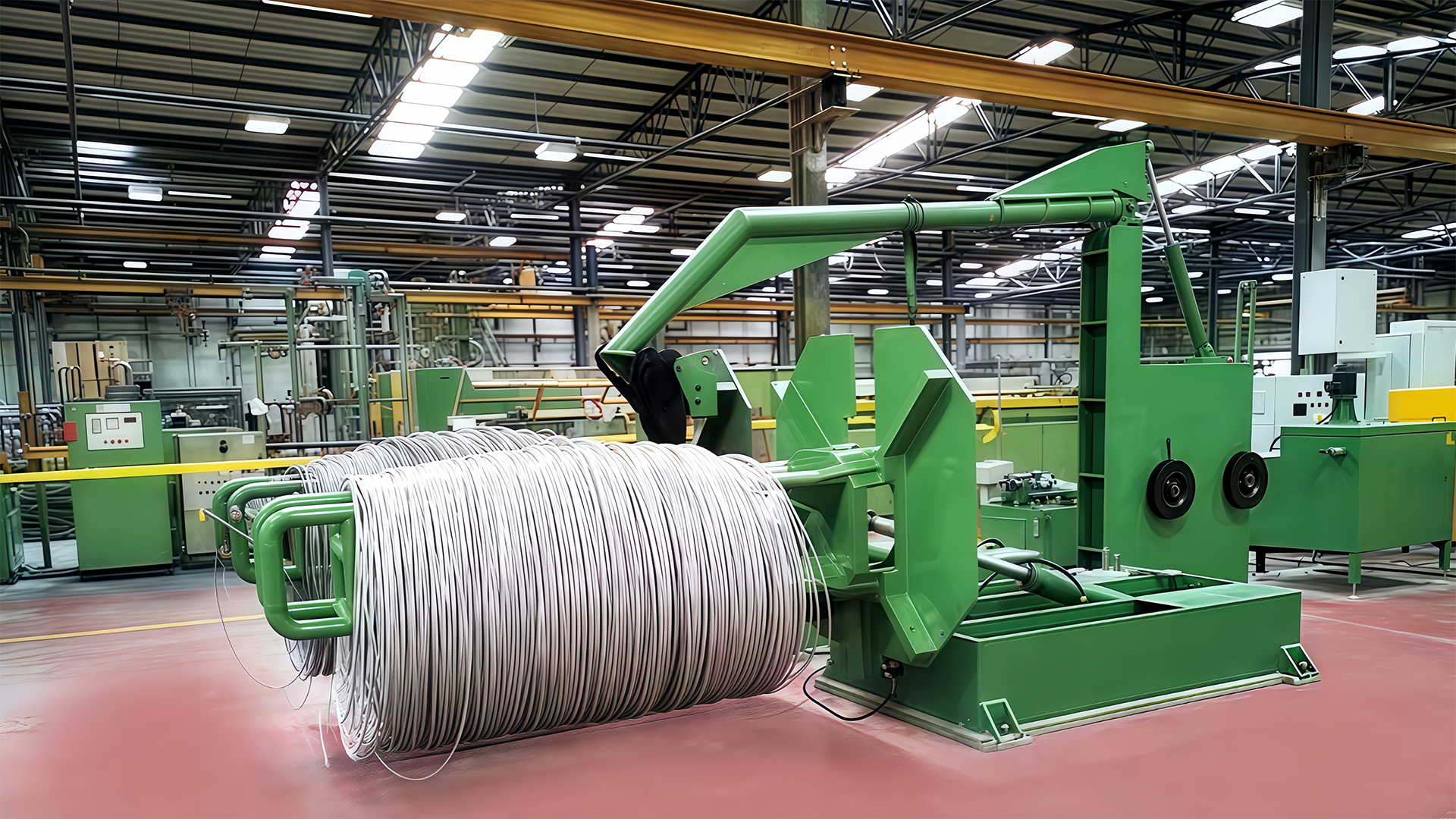
On the entry side, the practical question is how the coil is presented. A high-level pay-off keeps the wire running in a straight, low-friction line into the first die. A flip-type overhead pay-off machine adds the ability to load at floor level and then raise the coil into working position, which shortens loading time and reduces the risk of coil damage during handling.
On the exit side, the take-up decides coil shape, package weight and how easily the wire unwinds at the next process. Spool take-ups suit wire that will be shipped on a carrier; formers and winders suit wire heading straight into a nail press or a mesh loom.
Matching the three units is where a supplier with a full equipment range earns its keep. Jinding Technology, for example, builds drawing machines, pay-off stands, take-up units and the nail-making and auxiliary equipment that follows them, which makes it easier to hold one tension philosophy across the whole line.
Warning A pay-off that supplies wire at fluctuating tension shows up as diameter variation, not as a visible fault at the pay-off itself. If finished wire drifts out of tolerance, check tension control before adjusting die geometry.
What to Confirm Before You Place an Order
Most of these points cost nothing to check and a great deal to correct later.
- Input material and coil weight. Rod diameter, coil mass and coil geometry decide whether the pay-off can be loaded safely and whether a vertical layout is justified at all.
- Target gauge and tolerance. State the finished diameter and its allowable variation, not just the reduction ratio; downstream nail and mesh machines are far less forgiving than the drawing process.
- Take-up format. Spool, former or loose coil, plus the package weight the next process can accept.
- Building clearances. Headroom for the pay-off and the drum stack, and a floor that can carry the machine foundation and the coil handling route.
- Lubrication and die plan. Dry drawing with powder or wet drawing with liquid lubricant, matched to the die sequence and the material being drawn.
- Compliance paperwork. CE marking and an ISO 9001 based quality system are the baseline for exported equipment; confirm they travel with the machine.
Info Suppliers who build more than one drawing architecture will usually say so when a different route suits your material better. That conversation is worth having before the order rather than after installation.
Limits and Selection Risks Worth Knowing
The inverted vertical layout is not a universal upgrade. Fine wire in the hundredths of a millimetre range generally belongs on wet water tank machines, where the wire is fully submerged and lubrication and cooling work differently. Very small batches often do not justify the foundation and handling equipment a vertical line requires; a pulley machine will produce acceptable wire for far less capital.
There is also a hidden dependency. Vertical machines assume vertical handling. If coils arrive on a low pallet and the plant has no lifting equipment, the time saved at the take-up is simply spent at the pay-off.
Danger Do not convert an existing horizontal drawing line to a vertical take-up without measuring the full vertical clearance and floor loading. A machine that fits on paper can still be unusable once coil handling equipment is added.
Success When the pay-off, the drawing machine and the take-up are chosen against the same tension and package targets, the line runs at its rated speed from the first week and stays there.
The applications of the inverted vertical wire drawing machine sit in a fairly narrow but valuable band: heavy rod input, intermediate and medium gauge output, large packages, and a plant that would rather grow upward than outward. Inside that band the layout reduces handling, stabilises the wire path and shortens the line. Outside it, very fine wire, wet lubrication and tiny batches are handled better and more cheaply by other architectures.
The sensible sequence is to define the material, the gauge and the package first, then choose the drawing route that fits them, then match pay-off and take-up to the same tension targets. When those three decisions are made together, the drawing machine stops being the constraint and starts behaving like the middle of a production line instead of the end of one.