 English
 русский
 عربى
عربى

Mechanical Engineering — Manufacturing Series
The Quiet Physics of Wire Drawing
Inside the mechanical choreography that turns a thick metal rod into a hair-thin strand — one die, one pull, one micron at a time.
A Process Built on Tension, Not Force
There is a particular kind of elegance in wire drawing — a process that looks almost effortless from the outside, yet is governed by exacting mechanical principles beneath the surface. As metal rod is pulled through a series of hardened dies, it does not lose material. It is reshaped, elongated, and refined through pure tensile deformation.
Each pass through a die compresses the wire's diameter while stretching its length, following the immutable law of volume conservation. The result is a continuous transformation — not cutting, not grinding, but reshaping under controlled stress.
Inside the Die: Three Invisible Zones
Every die, regardless of size or material, contains three functional regions that the wire passes through in sequence. Understanding these zones explains why drawn wire achieves such remarkable dimensional consistency.
- Entry Zone — lubricant is drawn into the die, preparing the surface for controlled contact.
- Reduction Zone — the wire is compressed radially, undergoing plastic deformation.
- Bearing Zone — a short calibration section that finalizes the exact diameter.
Strain Hardening — Strength Earned Through Resistance
As the wire's internal grains stretch and elongate, dislocations within the crystal lattice begin to multiply. This microscopic resistance is what metallurgists call strain hardening — a phenomenon where the metal becomes progressively stronger, yet more brittle, with each successive pass.
A copper rod entering the line at roughly 220 MPa in tensile strength can exceed 400 MPa after several drawing passes — without a single degree of applied heat.
This is why annealing is so often woven into the production line — not as an afterthought, but as a
necessary counterbalance to the very strength the process creates.
copper wire drawing machine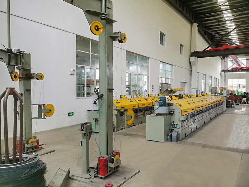
A Typical Reduction Schedule
The table below illustrates how a copper rod progressively narrows across four drawing passes, each governed by a calculated area reduction ratio.
| Pass | Area Reduction | Diameter (mm) |
|---|---|---|
| Feedstock | — | 8.00 |
| Pass 1 | 22% | 7.05 |
| Pass 2 | 20% | 6.30 |
| Pass 3 | 18% | 5.70 |
| Pass 4 | 17% | 5.15 |
Friction, Heat, and the Role of Lubrication
Friction is the silent adversary of every drawing line. Left unmanaged, it generates heat, accelerates die wear, and distorts the wire's final dimensions. Lubrication exists to interrupt this — a thin mechanical barrier between metal and metal.
Note
Wet drawing systems, which submerge dies in a circulating lubricant-coolant emulsion, are the standard for fine and medium-gauge copper wire due to the higher speeds involved.
Where dry contact might produce a coefficient of friction near 0.15–0.20, proper lubrication can lower this to as little as 0.03–0.05 — extending die life by a factor of five to ten.
When the Mechanics Go Wrong
Caution
Excessive tension or an overly aggressive reduction ratio in a single pass can cause the wire to neck and fracture before it clears the die — one of the most common causes of unplanned downtime.
Best Practice
Distributing reduction evenly across multiple passes, paired with synchronized capstan speeds, keeps tension within a safe margin and preserves wire integrity.
Closing Thought
Wire drawing is, in the end, an act of disciplined restraint — a process where strength is built not by adding material, but by carefully controlling how much stress the metal is allowed to bear at any given moment. It is mechanical engineering practiced with the patience of craftsmanship, one die, one pass, one micron at a time.